Enabling GT911 Touchscreen on Raspberry Pi Zero 2W with Yocto
A step-by-step guide to configuring Yocto recipes and hardware setup for the GT911 touch controller
February 4, 2026
Enabling GT911 Touchscreen on Raspberry Pi Zero 2W with Yocto
I purchased a 7.5-inch E-Ink display and a touchscreen to create my own E-paper device based on the Raspberry Pi Zero 2W.
It's a Goodix product that combines an E-Ink display with a GT911 touchscreen. I bought it without hesitation as it was on sale at a low price on Amazon.
It's a Goodix product that combines an E-Ink display with a GT911 touchscreen. I bought it without hesitation as it was on sale at a low price on Amazon.
I'm going to modify the meta-jooojub-rpi layer created in a previous post to enable the touchscreen and E-Ink display.
In this post, I'll focus on enabling the GT911 touchscreen first.
1. Hardware Setup
The Goodix product I purchased is as follows:
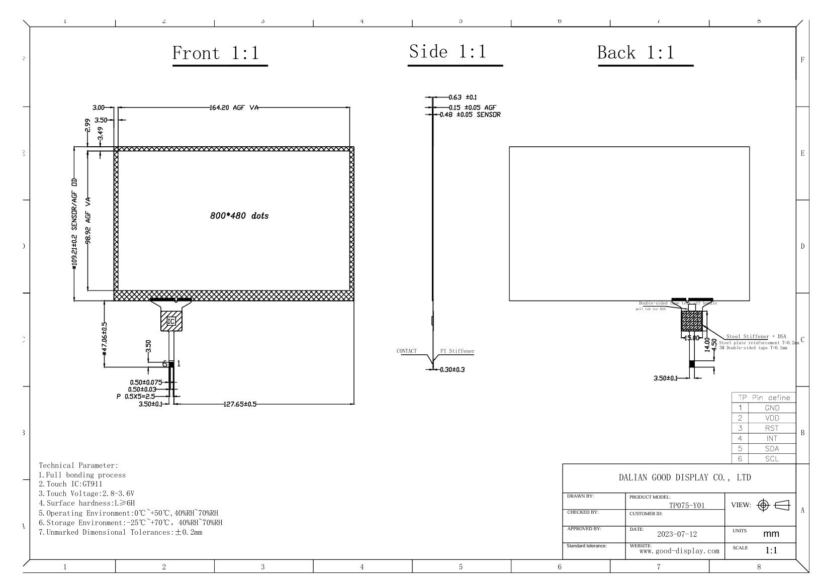
- GDEY075T7-T01: https://www.good-display.com/product/483.html
According to the specification drawing, the touchscreen uses the GT911 IC and communicates via I2C.
The E-Ink display uses SPI and appears to require a separate controller.
The E-Ink display uses SPI and appears to require a separate controller.
Fortunately, I was able to use an E-Ink display controller I already had.
The issue was the touchscreen; I didn't have a spare connector for the FPC connection, so I had to order one separately online.
The issue was the touchscreen; I didn't have a spare connector for the FPC connection, so I had to order one separately online.
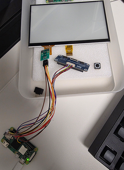
I connected the GPIOs by referring to the pin map, and the final hardware configuration is as follows.
I wanted to test it with sample code immediately, but I decided to configure the image with Yocto first.
2. Modifying Yocto Recipes - DT overlay
I discovered an overlay DT in the latest Raspberry Pi kernel source. It seems this can be used to easily enable the touchscreen.
To apply the desired modifications, copy the goodix-overlay.dts file to an appropriate location within meta-jooojub-rpi and configure it to be copied during the Yocto build.
You can create a .bbappend file to add or remove specific behaviors while keeping the original kernel build intact.
Add the following file to meta-jooojub-rpi to use the goodix overlay.
Add the following file to meta-jooojub-rpi to use the goodix overlay.
recipes-kernel/linux/linux-raspberrypi_%.bbappendbitbake
Now, create a files directory, copy goodix-overlay.dts, and modify the values as needed.
I added size-x, size-y, and the actual physical sizes according to my hardware configuration.
Additionally, since I plan to use the touchscreen vertically, I added inverted-x and swapped-x-y.
I added size-x, size-y, and the actual physical sizes according to my hardware configuration.
Additionally, since I plan to use the touchscreen vertically, I added inverted-x and swapped-x-y.
recipes-kernel/linux/files/goodix-overlay.dtsDevice Tree
Now, I need to add dtoverlay=goodix to the Raspberry Pi config. Looking at meta-raspberrypi, it seems this can be configured via RPI_EXTRA_CONFIG.
These settings can be added to the previously created distro.
While I'm at it, I'll also add settings for I2C and switch the init manager from the default sysvinit to systemd.
While I'm at it, I'll also add settings for I2C and switch the init manager from the default sysvinit to systemd.
conf/distro/rpi0-2w.confdiff
3. Modifying Yocto Recipes - GT911 firmware
After building and booting, I saw that goodix was probed correctly, but a message appeared stating that the firmware was missing.
Attempting to load firmwareshell
Looking into the goodix driver code, I found that the 'firmware' refers to the configuration values used by the GT911.
drivers/input/touchscreen/goodix.c - goodix_config_cbc
drivers/input/touchscreen/goodix.c - goodix_config_cb, goodix_send_cfgc
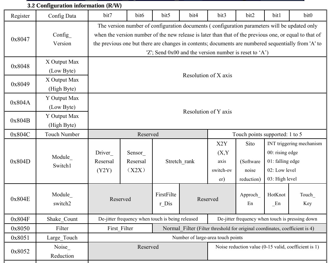
Referring to the GT911's rather unhelpful manual, I confirmed that 0x8047 corresponds to Configuration Information (R/W).
I had to set up the firmware according to my hardware configuration, but Goodix did not provide any specific firmware.
With only the insufficient GT911 developer manual and using RAG with an LLM, I had no choice but to create the firmware through meticulous trial and error.
With only the insufficient GT911 developer manual and using RAG with an LLM, I had no choice but to create the firmware through meticulous trial and error.
I then packaged the resulting goodix_911_cfg.bin file so that Yocto copies it to the desired location during the build.
Creating a package in Yocto is straightforward.
Just create a .bb file with the desired package name and add it to IMAGE_INSTALL.
Just create a .bb file with the desired package name and add it to IMAGE_INSTALL.
recipes-bsp/goodix-firmware/goodix-firmware.bbbitbake
4. Modifying Yocto Recipes - INSTALL packages
Finally, modify the image recipe to install the necessary packages.
I've also added several packages that I expect to need later.
I've also added several packages that I expect to need later.
recipes-core/images/jooojub-rpi0-2w.bbdiff
5. Build and test
Now, let's build the image and test if the touchscreen works correctly.
Build and flashing to SD Cardshell
After flashing the built image and booting, the previous firmware load failure logs have disappeared.
Attempting to load firmwareshell
Checking with i2c-detect, it seems to have been probed without any issues.
i2cdetectshell
Performing a touch test with evtest, the desired events are being reported correctly.
evtestshell
6. Next Steps
I've added the firmware and DT files for probing the GT911 touchscreen to Yocto, allowing them to be used immediately in the built image.
Next, I'll apply the modifications to enable the E-Ink display in meta-jooojub-rpi.
7. On a side note
On a side note, I had set this aside for several months because the I2C probe kept failing.
Just in case, I measured the 3V GPIO with a power meter and discovered that no voltage was being applied.
Just in case, I measured the 3V GPIO with a power meter and discovered that no voltage was being applied.
I was struggling so hard to enable a controller that didn't even have current flowing to it. T-T
In the end, it turned out to be a soldering issue with the GPIO pin header.
In the end, it turned out to be a soldering issue with the GPIO pin header.